Entity Relation Diagram is part of the data modelling process ant it’s the representation of a relational database. Whenever a database has to be created, this diagram acts as a blueprint to have a complete overview and to ease the creation process. Furthermore, after the database has been created, ERD helps both specialized, and non-specialized, people to understand its structure.
Data Modelling
A Data Model is the foundation of building data warehouses and business intelligence. Helping build conceptual, logical and physical models with clearly defined relationships is the primary goal of a Data Model. Furthermore, it provides a visual way to communicate between people and businesses.
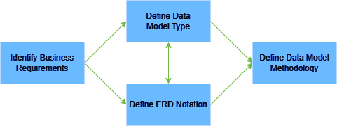
Data Modelling is the process of creating a Data Model by identifying business requirements. It is composed of mainly three steps:
- Identification of Business Requirements, via meetings, interviews and review of existing processes
- Definition of ERD Notation, choosing between IE, Chen’s Style or UML
- Definition of the Data Model Type, conceptual, logical or physical
- Definition of the Data Modelling Methodology, choosing among a Relational Data Model or a Dimensional Model
Entity Relation Diagram Notation
The ERD Notation uses four building blocks to contextualize business data:
- Entity, the object from where data is collected and must have attributes
- Attributes, entity properties that can be descriptors or identifiers
- Relationship, the connection between entities
The ERD creates a visual representation of entities and relations, providing how tables of a database should connect and which columns such tables should have.
IE Notation Style
For its simplicity and readability, the Data Modelling field widely uses the Informational Engineering (IE) Notation. The modelling of an e-commerce will serve as an example to explain this notation.
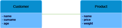
An Entity is a class of object, represented by a rectangle. This can be something that exists in the real world logically, physically or conceptually. In our example it can be represented as a product. The entity lists the Attributes that describe it. For a product, its Attributes could be the price, the name and the weight.

One Entity connects to another through a relationship, which a straight line represents. A Relation between a customer and a product exists, for example, because the customer can buy a product from the e-commerce site.
In a Relationship, the cardinality must be specified: cardinality defines the possible number of occurences between entities. So, for example, a customer can also buy many products, and not a single one.
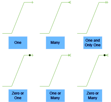
To represent cardinality, the ends of a Relationship line change according to the type of relation between the entities. The types of ends can be of six types:
- One, the entity can only be present one time
- Many, the entity can be present many times
- One and Only One, the entity can only be present one, and only one, time
- Zero or One, the entity can be present zero or one time
- One or Many, the entity can be present many times but at least one time
- Zero or Many, the entity can be present zero or many times
Examples for Cardinality
Now some examples to make all concepts about cardinality clearer. Note that both ends of the Relationship must contain information about cardinality: one end will refer to an Entity and the other one to the other Entity (in some cases a line with no ends can be present, in that case it represents a One relation).
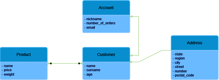
To describe a One Relation, we can think about a customer that has an address associated to it. The customer has only one address but this could change in the future. The address on the other hand, could have many customers related to it , resulting in a Many Relationship: two customers could live in the same building but in different flats. The address Entity does not have any information about floor or door, which enforces this example. In a real situation, this relation should be treated as a One.

The entity account has a One and Only One relationship with the customer: the e-commerce assigns one customer to one account and never changes. On the other hand, a single customer can only have One and Only One account associated with them.

The customer may buy no products when registering to the e-commerce site, perhaps waiting for some discounts. This translates into a Zero or Many Relationship. However, many customers can buy many products, but some products may remain in stock without any buyers. This situation results also in a Zero or Many Relationship.

Now, if we try to make one single diagram, it should look something like this. Real situations with many more entities and relations can further expand this simple example.
ERD Model Types
The Logical Data Model is a particular type of diagram that the Entity Relation Diagram described so far represents. As years passed, the introduction of different types of ERD models helped to achieve different goals and to have different abstraction levels on the problem. There are three types of models.
Conceptual Data Model
The Conceptual Data Model is a simplified high view version of ERD with goal of acting as a business requirements reference and a communication tool within the business. Its features are:
- shows Entities and Relationships but without Attributes
- independent of the database management system
Logical Data Model
The Logical Data Model identifies how the entities must behave between each other. For this purpose, the Conceptual Data Model gets more information on top of it to achieve further levels of detail. Its features are:
- shows Entities and cardinality of Relations
- has Primary and Foreign Keys
- all Attributes are specified within entities
- independent from the database management system
Physical Data Model
The Physical Data Model identifies the implementation for a specific database management system and acts as a plan for the developer. However, the final result can change from the Logical Data Model since tables can be added or removed in order to achieve specific functions. Its characteristics are:
- Entities are table names and Relations are specified with cardinality
- Attributes become the column names
- each Attribute has a data type, an optional length of the field and the indication on whether it is nullable or not
The following table recaps differences and similarities.
| Feature | Conceptual Model | Logical Model | Physical Model |
|---|---|---|---|
| Entity Names | ✔️ | ✔️ | ✔️ |
| Entity Relantionships | ✔️ | ✔️ | ✔️ |
| Relationship Cardinality | ✔️ | ✔️ | |
| Attributes | ✔️ | ✔️ | |
| Table Names and Column Names | ✔️ | ||
| Data Types | ✔️ | ||
| Primary and Foreign Keys | ✔️ | ||
| Target Audience | Business | Architect | Developer |
All the diagrams in this blog post have been created using the free software draw.io, which can be found here.
If you want to read more posts about databases click here.